Holes - Counterboring
![]()
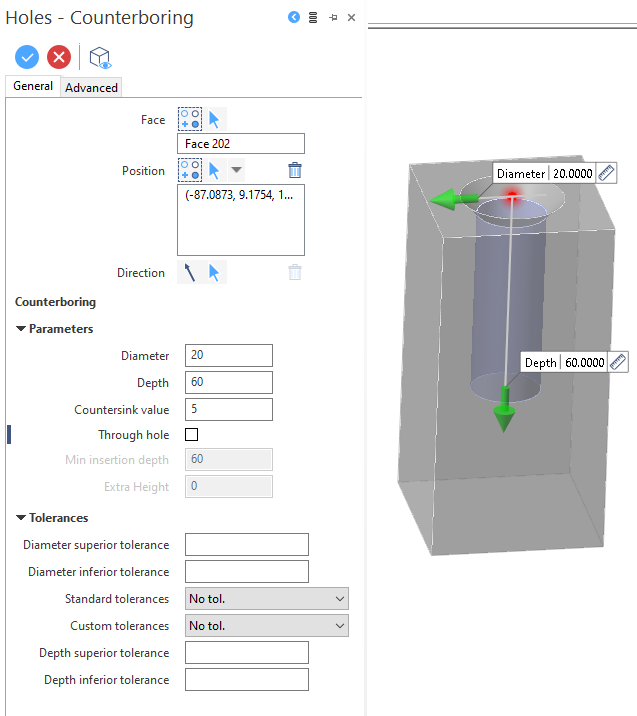
When selecting this feature type, the Holes - Counterboring - Options tab is displayed along with the ribbon containing the Options and Filters sections. At the same time, the Holes - Counterboring dialog box is displayed. ![]() See dialog box.
See dialog box.
Procedure
- Select the face on which the counterbore must be created.
- Select one or several feature positions.
- If required, select the feature axis direction.
- Using the sliders in the graphic area, their input fields and/or the input fields in the dialog box, define the feature parameters.
- If necessary, define the Tolerances by unfolding the corresponding section.
-
Validate, either by a Right Mouse click or by clicking the
 icon in the dialog box.
![]() Notes:
Notes:
- You may click the active slider arrow to adjust the value of the corresponding dimension in the value input box of the slider label.
-
Refer to the Slider Positioning and Movement section for further information about slider usage.
-
You can use simple JavaScript expressions and mathematical formulas to define the required values.
- Clicking on the Measurement
 icon on the slider label or alongside the active value input field in the dialog box displays the Measurement Menu which helps you to define specific points.
Dialog Box Options - General Tab
The following options are available in the Holes - Counterboring dialog box:
Top Toolbar
![]()
![]()
![]()
These two icons at the top of the dialog box allow you to Apply the current values or to Cancel the current function.
Preview generation is Automatic if this option is active in the dialog box menu accessed by clicking on the  icon. If this option is not active, click on the
 ![]() icon. If preview generation is not possible, the icon is greyed out.
icon. If preview generation is not possible, the icon is greyed out.
Face
Defines the reference face on which the hole feature will be created.
Clicking on the ![]()
![]() icon switches back into the selection mode allowing you to modify your selection by selecting/unselecting elements in the graphic area. You may click the
icon switches back into the selection mode allowing you to modify your selection by selecting/unselecting elements in the graphic area. You may click the ![]() icon and then click Reset selection to reset your whole selection. If you want to delete elements within your selection, select the required elements and then click the
icon and then click Reset selection to reset your whole selection. If you want to delete elements within your selection, select the required elements and then click the ![]() icon above the list field. You may use the [Ctrl] + [A] shortcut to select all of the elements.
icon above the list field. You may use the [Ctrl] + [A] shortcut to select all of the elements.
Direction
By default, the hole feature is created normal to the selected position. You may use this option to define another feature axis direction.
Parameters
|
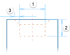
Diameter |
Diameter of the counterbore that will be created. (1) |
|
Depth |
Depth of the counterbore that will be created. (2) |
|
Countersink value |
Value of the chamfer that will be created on the edge of the selected element. (3) |
|
Through hole |
Check the box if the counterbore to be created is a through hole. |
Tolerances
Refer to Holes - Tolerances.
Information Field
The field at the bottom of the dialog box displays information about missing data, errors or actions.
Advanced Tab
Refer to Holes - Advanced Tab.
For further information...
- Holes
- Hole Settings
- Holes - Drilling
- Holes - Tapping
- Holes - Conic Tapping
- Holes - Male Thread
- Holes - Counterboring + Drilling
- Holes - Counterboring + Drilling + Counterboring
- Holes - Counterboring + Drill for Screws
- Holes - Counterboring for Screws
- Holes - Drilling for Screws
- Holes - Modify hole